Production and sales of metal injection molding (MIM) parts
Technical information
|
3D-μMIM technology will enhance the design freedom even more |
|
■Metal injection moulding (MIM) process
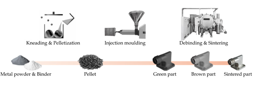
This image shows the overview of Metal injection moulding (MIM) process. The material used for MIM is called feedstock, which is made of polymer, wax mixture and metal powder. The feedstock will be injected into the net-shape cavity of the mould to form the component. The injected part is called green body and this green body is debinded and sintered to be the final metal component.
■Comparison to other processing
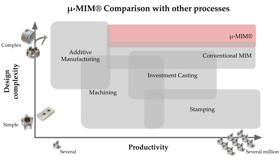
This image shows the characteristics of each manufacturing method against the productivity and design complexity or design freedom. As you can see, MIM is good at relatively complicated designed parts’ serial production. Our μ-MIM® technology enhance the metal components design freedom.
■Material varietyMIM is a powder metallurgy method, therefore, it is applicable to high-melting point or difficult to cut material. On the other hand, it requires the feedstock development for small size powder. Thus the material variety is limited compared to press and sintered method. μ-MIM® provide the widest variety of material option among the MIM manufacturer. |
|
||||||||||||||||||||
■Difference between conventional MIM and μ-MIM®
This table shows the unique strong points of μ-MIM®. We focus on small complicated metal components’ mass production.
Thus, we are competitive on the tolerance achievement and thin wall thickness.
| μ-MIM® | Conventional MIM | |
| Tolerance range (mm) < 5 mm |
±0.01 | ±0.03 |
| Relative density (%) | >98.5 | 95 - 98 |
| Wall thickness (mm) | 0.1 (< 5 mm sq.) | 0.3 (Partially) |
■3D-μMIM technology will enhance the design freedom even more
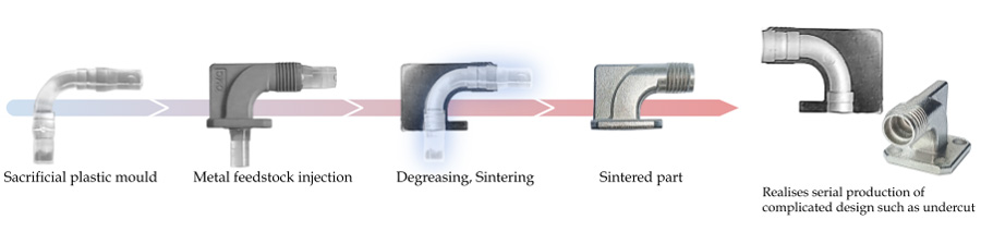
This is a 3D-μMIM processing image. This method will realise the serial production of difficult to produce in metal component production with uniform quality. For example, the inner curved, under-cut, interior channel, difficult to de-mould design are applicable to 3D-μMIM production.
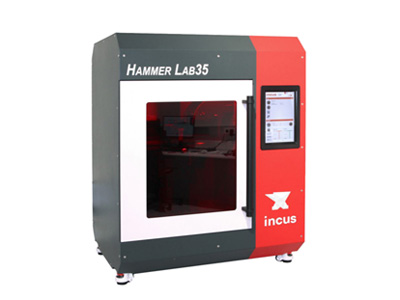
■3.5D Printing will reduce the trial periodWe develop a new technology, 3.5D printing technology which is a fusion of the latest 3D metal printing technology and μ-MIM® technology. This image shows our newly introduced 3D printing machine using lithography based metal manufacturing method. This machine will reduce the green part production time in small quantity production, thus it is beneficial for trial. The debinding and sintering process will be applied our μ-MIM® technology, therefore the technical gap between the trial and mass production is minimal yet the shorten the trial time drastically. |
 |
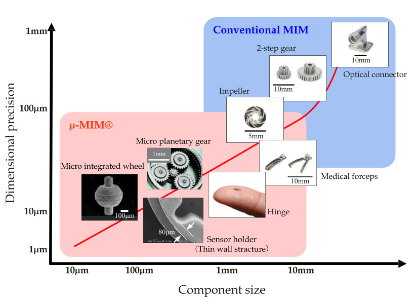
■μ-MIM® territory
This graph shows the technical targeting area of conventional MIM and μ-MIM®. μ-MIM® defies your understanding of MIM.
We will satisfy your tolerance requirement in small complicated designed serial production with highly controlled quality.